
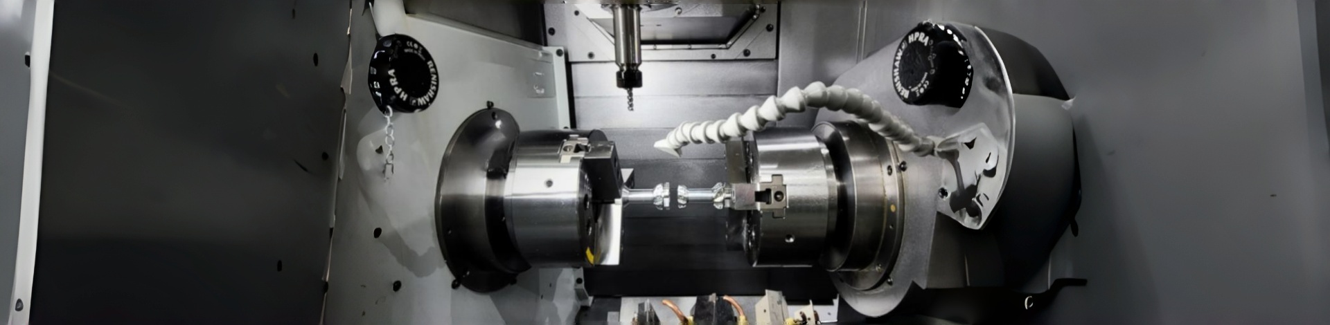
CNC Machining
When you're drawing, everything seems fine—dimensions are clearly marked, and the model looks beautiful. But then the drawings are sent to the workshop, and the machinist takes one look and shakes their head. Either they say "the tool can't get down there," or the finished parts turn out to be scrap. Where's the problem? Here are the six most common mistakes we tend to make.
Too many sharp corners, with no fillets left on internal corners
A sharp corner on the drawing looks clean and neat, but an end mill is round. If the internal corner is a sharp 90° angle, the tool simply can't reach the bottom, so you have to switch to EDM (electrical discharge machining), which is slow and expensive. In reality, just changing that internal corner to an R0.5 fillet allows the end mill to run through smoothly, doubling efficiency and bringing costs down.
The slot is too deep for the tool to reach
The slot is 20mm deep, but the opening is only 6mm wide—how far do you expect the end mill to extend? The tool sticks out as a long, slender shaft, and as soon as it starts cutting, it chatters and snaps. When designing, think about it first: can the tool even reach down that deep? And if it can, is the rigidity still adequate?
The wall is too thin and deforms under clamping
A wall thickness of 0.5mm does look delicate on the drawing, but on the machine it bends when clamped, vibrates when milled, and the finished part ends up looking like a potato chip. Thin-walled parts aren't impossible to make—you either work around it with smarter fixturing, or add a few stiffening ribs during the design phase and cut them off afterward.
Every dimension is toleranced at ±0.01
It sure looks "precision," but the cost can multiply several times over. In reality, most surfaces don't need such tight tolerances. Only the mating surfaces where bearings go or parts fit together require tight control. Elsewhere, loosening to ±0.1 or even wider won't affect functionality at all, but it'll save you a big chunk of machining costs.
The bottom of the hole is drawn as pointed, but the end mill is flat
The bottom of a blind hole is drawn with a sharp point, but end mills have flat bottoms (with at most a small corner radius). The machined bottom will naturally be flat, which doesn't match the drawing. If a flat bottom is absolutely necessary, either specify a flat-bottom end mill or leave some stock for EDM to clean up the corner.
The entire part is all surfaces, with nowhere to clamp
The design focused only on aesthetics, without thinking about where the fixture would grip. It's only when machining begins that you realize every surface of the part needs to be machined, leaving no place for the jaws to grab. During the design phase, plan ahead by leaving two process bosses or a clamping reference surface, and just cut them off when machining is complete.

0086 0755 23170739
0086-0755-24325235
ciky@hainamould.com
Room 1605, 16th Floor, Hongyu Building, No. 495, Donghuan 2nd Road, Longhua Subdistrict, Longhua District, Shenzhen, Gongdong ,China 518109


Copyright 2026 Hainamould.com All rights reserved.
-
 0086 0755 23170739
-
 Facebook
-
 WhatsApp
-
 LinkedIn
-
 TOP
TOP